

THE358BANSH
-
Posts
402 -
Joined
-
Last visited
Content Type
Profiles
Forums
Events
Gallery
Store
Everything posted by THE358BANSH
-
No big deal, there is just a ton of people that think this is easy as you know with your prior experience. Were you using a HEI module to convert the signal using the stock flywheel? On to the subject at hand... IIRC using anything above version 2.8 code gives the ability to use the "dual spark" function. This allows for a myriad of configuration using two sensors for input and thus being able to drive two separate outputs. For the 36-1 wheel, it was built using the generally accepted methods outlined in the MIcroSquirt manual for trying to obtain the cleanest signal possible. I turned the OD of the flywheel to 5.0000" on the lathe, knocking the stock pickup nodes off in the process. The ID of the trigger wheel was 5.0005" for a nice fit on the flywheel. After locating the trigger wheel on the flywheel with four small welds, I turned the OD of the trigger wheel again to verify it was concentric around the crankshaft centerline to maintain an even pickup gap. The stock pickup on the stator was reused being as it's a variable reluctance deal. I just verified the signal with an oscilloscope to figure out rising edge or falling edge. Set the gap at .020", and double checked the sensor gap while rotating the flywheel. After that it's not too bad. Figure out the number of teeth after the missing tooth when piston #1 is at TDC and enter that, the skip 18 teeth to fire output #2. I am using the LS2 coils, so the MicroSquirt was converted to logic level outputs as described earlier in this thread. Last but not least everything was verified using the "tooth analyzer" firmware to double check functionality. I don't know if that answers most of the fabrication side of things, but I'll list some links below that are just as important for nitty gritty info in the configuration state of things. Evan http://www.microsquirt.info/dualspark.htm <---I'm using the 3A setup in here... http://www.megamanual.com/ms2/wheel.htm http://www.megamanual.com/seq/coils.htm#ls2 http://www.microsquirt.info/tachref.htm
-
Thanks for the words guys. There is a bunch of really smart people on this forum that I have learned a ton from. Now that I am not a dumbass anymore, I try and give back to keep the forum new and interesting. Banshees will always be the best! Depends on why you want them. The research and configuring process are the most tedious parts of the build. If you do not want to learn the how to and why of making the system/tune up, MegaSquirt/MicroSquirt or one of it's variants is not for you. If you are looking for a tuneup so you can toss it in and not have to do the legwork, you are in the wrong place and won't get any help from this guy. If you need help and/or have a few questions on configurations, I would be more than willing to try and be of assistance. Let me know... Another good night of progress was made. With the help of MattSCES on the shout box last night we found a key that should work. It's not as nice as the LTR deal i wanted, but it was only 22 dollars instead of a minimum of 60 dollars for a used unit. Hopefully, it should be here on Friday so I can button this up. Tonight I got the front suspension reassembled. The color of the arms is crimson red and dang is it bright! Next was swapping out the studded tires for the summer set. I even had a chance to move the brake lines in the process. I tossed the plastic on temporarily so I could clean the shop for a bit and then decided to take off. Later, Evan
-
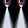
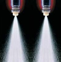
Negative, that's a customers car. I don't know if I could ever bring myself to own one of those. Hell, I'd take a turbo 2.3 in a mustang(gasp) before you would see me in one, and I'm die hard GM... Thanks for the words guys. I got the rest of everything buttoned up last night after I noticed I made a mistake. I accidentally put the intake manifold boots on upside down, thus blocking part of the injector spray path. I ended up taking them off, building a thicker(.125") reed plate thingy, flipping them over and reinstalling and then redoing the crankcase pressure test. Welded up the coil mounts, and spritzed some paint on everything. I also managed to find a small trans leak this morning when I came in. Probably going to leave it for now, no sense in taking it out to fix that only to possibly have to take it out later. Fired it and took a little video tonight after ripping the front suspension off for powdercoat/rebuilding shocks. I have a small list to get done before riding it. Bunch of little stuff now more than anything. Not 100% for sure if or when I am going to dyno it. I don't know if it would be a benefit as of now. I think I will work on the tune around the shops field and road to get it real close, then take it over to Janssen Motorsports and play for an afternoon. Weather has been all kinds of crap here as of late so I'm thinking the ice is done for the year. List is below, hopefully should be done for Friday so I can play this weekend...Later, Evan Need to find key switch/install Change tires over to dirt set Check chain slack Reassemble front suspension Reroute front brake lines Plastics Build air filter to throttle body tubes Clean filters Build ground cable for engine/chassis/battery Wire HIDs and some other stuff that probably isn't that important...
-
I got a chance to play for a few hours here tonight. My list kind of got tossed by the wayside, and I just wanted to get it fired so I only did what was needed. First was establish a TDC location, so that I could build a timing pointer to double check spark advance. I made a mark on the flywheel at .050" BTDC, and .050" ATDC. Busted out the dial caliper and split the difference to find true TDC and then made a mark there. Next for the to-do list was to check squish and everything checked out fine. After getting everything ready to fire I double check all of the configuration in the software. I then used a program called Tooth Analyzer to double check my crank trigger wheel design, sensor gap, and polarity. After giving ignition power a few times to cycle the fuel pump, I found a few small leaks and took care of them. I gave the entire quad the once of a century, and gave it a kick. Nothing happened. Fortunately, I had forgotten to connect my igntion jumper wire after the fuel leak! Connected that and gave it another shot and she fired up, but only on one cylinder. After going back and looking at the configuration, I noticed I missed an important drop down menu which controls the firing event for cylinder #2. Gave that a shot, rebooted the ecu and kicked again. This time we were golden and banging on both holes.<---Sounds dirty huh? I wanted to get a complete warm up cycle on it before I left. Everything went well , no leaks other than the fuel ones earlier. One of these days I'll have to sandblast and paint those a-arms. They are sticking out like a sore thumb. I even took a video for all you dudes, not the greatest quality but it works... Later, Evan PAH! I sound like a canadian! EH?
-
Needs to be welded and trued at the same time. The welding will pull the crank out of true ever so slightly so it will need to be finessed after the welding is done...
-
Big update for tonight guys...I'm thinking tomorrow will be the day to see if it makes fire in the hole. The new 19cc domes and o-rings came last week and I finally got a chance to install them. It's got a wee bit more compression now, I can't wait. I finished up the EFI wiring, except for the key switch I still need to buy and the HIDs. Probably going to just rig up a toggle for tomorrows test fire. There are three relays for the entire system. Relay #1 provides ignition hot for the coils, injectors, ecu, and O2 sensor and is controlled using a ground circuit from the key, relay #2 controls the fuel pump by way of ground through the ecu, and relay #3 provides power for the entire lighting system triggering off the light switch ground. All power circuits are fused, with three of them being located on the front of the battery box. The small push button and LED is used for calibration of the O2 sensor and also functions as a system error/diagnostic tool. The TrailTech regulator/rectifiers bolted up directly in place of the stock voltage regulator and cdi, kind of a nice surprise. I made a huge list of stuff to get done before firing it. Today tons of it got knocked out. The throttle cable I used for mock up was a tad bit short routing it the way I wanted and just a bit frayed on the end. I found out Motion Pro has a 2" extended version of the LTR cable so I went ahead and got one. I also acquired a ASV clutch lever from iDeal, the tape is temporary because I need to get the rebuild kit for it with the rotator clamp. I tossed all that stuff on and lubed/routed cables for a bit, double checking full lock and stuff. Next on the list was the crankcase pressure test. Ran to FleetFarm to get the parts and a bunch of random needed things. The exhaust plugs are 1.5" plumbing plugs and the intake needed a 1.5" pvc cap sanded down to 2.060" for the R6 intake boots. I had port matched the other intake boot last night, and built the little reed plate spacer things then assembled it before I left. I ended up having one small leak around a reed bolt. Resealed it and checked again to see everything okay. After the pressure test I mounted the fuel filter on the pressure side of the fuel system. Then ran a few vents for the trans and bolted the throttle bodies in the process. The return line for the fuel pressure regulator needed to be tee'd into the vent for the pump housing, so I built a small fitting and plumbed a line for it in the process. Rebuilt the kicker, filled it with oil and coolant and then got some fuel for tomorrow. Things to do before starting... Calibrate 02 sensor Communicate/recalibrate EFI sensors Double check everything Build ground cable for engine/chassis/battery Compression check Hope for the best, expect the worst Things to do before riding... Build air filter extension tubes/mounts Mount IAT sensor in filter tube Source and final wire key switch/tether Install HIDs Sync throttle bodies Weld broken nerf bracket Clean/paint everything Give it the once over of the century And I'm sure there is more than a few things I'm forgetting, but those above are the big ones....Evan
-
Sorry about not seeing that, replied... Yeah, everyone has their own idea of what performance is. Engine is fresh with a forged crank, Crower rods, JE pistons and a bunch of head work. A "little" turbo with a Accel Gen 7 KIt and she'll be ready to fly... On another note, I have been super busy and not had a chance to update my progress. Expect one later tonight...
-
Whos unit did you use? Got any pictures? I floated the ground on the stator tonight, and changed the connectors over. It now has seven wires, two for the source coil, two for the pickup coil, two for the lighting output at 125w each, and the floated ground. After that I finalized the sub harness for the throttle bodies and sensors. It includes everything for tps, map, iat, injector 1, and injector 2. Tossed the stator in place to double check some stuff, ran a few extra wires, and then connectorized the whole deal. I still need to sheath and terminate the three large wires in the last picture, they will go to the engine and ground using one of the case bolts. Tired and hungry, I'm out...Evan
-
Thanks Mike...You ever come up with a price for the RZ parts? How cool would a EFI powervalved banshee be? I played around tonight and started finalizing the wiring and routing of junk. For the most part I just started at the front and moved my way back towards the battery trying to keep in mind all other wiring that may be affected by what I was working on currently. So far the serial port for the communications cable, both coils and the coolant temp sensor are permanently wired. All of the temp sensors for the MicroSquirt are negative temperature coefficient, which basically means as the temperature of the sensor increases, the resistance through the sensor drops proportionally. I needed some place to mount the GM temp sensor which has a 3/8npt inlet. The boss was over looking at the project while I was stumped and out of the blue says, "Why don't you just build an extension where that outlet bolts to?" I completely forgot the outlet was separate and felt so dumb, so I whittled out a sensor block out of some 1" thick aluminum plate. While mocking up most of the wiring, the oxygen sensor needed to be located. I decided to mount the sensor in the left expansion pipe. Most multi-cylinder engines with pinned cranks will have some amount of twist to the crank while running, and as a byproduct the stator side of the engine runs the hottest. The sensor is mounted in the belly of the pipe, just at the beginning of the baffle cone around the 2 o'clock position. The wiring for the sensor runs underneath and tight to the gas tank, then down the right side framerail to the lambda cable. As mentioned earlier, the extended bung was used to keep the sensor out of the direct airstream. Tomorrow will have the rest of the EFI wiring on the list. Still need to float the ground on the stator, and wire tps, map, iat, injectors, and a few other odds and ends. I also gotta take a second and thank my good friend Levi. He let me take parts off his LTR for mockup on my stuff and it made my life alot easier. His '06 has a ton of mods that we've done, and is a blast to ride. He'll probably never see this, but if he does it'll probably make his day. Thanks bud!
-
On most stuff using cromoly, you can use 70% of the mild steel wall thickness and be fine. It all depends on specific application at the end of the day...Evan
-
Thanks, it will be burned in permanent once I break the quad down for final assembly. The coils can be run sequentially or as a wasted spark setup, just depends on how the configuration is setup in the ecu. As for my time spent, I always have a winter project scheduled to do before I get back to working on the race car. It's just something different to do and break up the monotony of cars, cars and then more cars... That's Steve Murphy, the guy I mentioned earlier in one of the posts. I have checked out his site more than a few times. Hot tank washed, bead blasted, and then washed again. Unfortunately, the domes and o-rings didn't make it today because of the storm. I was really hoping to have them for the weekend but it gives me chance to get the other junk done. HID conversion kit showed today so I was pretty jacked to play with those for a bit. The coil bracket got tacked in place for mockup and wiring. Got bored then for a while and built plug wires seeing as they are needed too. Next on the list was mounting the ecu. I decided to mount it up behind the radiator on a small plate welded to the chassis. The radiator got moved forward in the process also. The convoluted tubing that's on the harness sucks balls. It can't make a tight turn without kinking and it is alot bigger than it needs to be. Ended up cutting it off and replacing the first few feet with some TechFlex product. The stuff is like a chinese finger trap, kinda dangerous for a simple mind like me. The wire bundle in the picture is all 35 wires for the system, and is only about the size of a nickel. After that I just played with wire routing for a while as seen in a few of the first pictures. Later, Evan
-
Glad everyone is enjoying this project as much as I am... I loaded the rolling chassis in the pickup and took it to the car wash to clean it up. I needed to get the motor and everything else mocked up one final time so I can decide where to mount the coils, ecu, and lambda cable. Needless to say, pressure washing with a wind chill of -1 degrees makes things a little chilly. Got back to the shop and decided I was sick of bending over or kneeling on the floor so I found a little stand in the back room to put the chassis on. it's kind of like the burgard cycle deal, just free so way cooler. I noticed I never took any decent pictures of the intake boots so here they are below. The right one is ported to the size of the reed stuffer, I just have to finish the little notch on the bottom for the injector spray path. The engine went in smooth, just waiting for domes that should be here tomorrow. Next on the list was mounting the ecu and coils. Both of these have to be placed well, with a few important things to keep in mind. RFI, wire routing, moisture, etc. are some of the big ones. I found a place suitable for the coils that I was happy with and built a little tube bracket to hold them. It turned out sweet and simple. Didn't get a chance to mount the ecu. So far I can't make up my mind as to exactly where I want to place it. Basically we've got three options, back by the battery, sandwiched in the area between the tank and seat above the throttle bodies, or in between the radiator and steering loop bracket. Back by the battery isn't bad, it's just the leads for the wiring get long and have to be in close quarters with the exhaust on the trip to the front. Mounted behind the gas tank makes all the leads nice and short, it just dumps the wiring right on top of the throttle bodies and makes it kind of cluttered. Option three by the radiator has probably the best pro/con ratio. The ecu would be out of the way of mud/dirt/moisture. The noisy leads for the coils would separate from the harness almost immediately so chances of RFI start to dwindle. Only real downside is space is at a premium up there. I played around for a while, and I figure I can build a spacer to shift the radiator forward about 1" on the top to give me adequate airlfow/clearance to the ecu. On the plus side my front Lakers have enough clearance to do this also. As it's rated the box can handle 105 degrees celcius~221 degrees farhenheit constant. I've never had a temp sensor in this engine so I am going by what I have heard, but most scenarios seems like 200 degrees is pretty hot for one of these engines. I have only heard of big motors getting that hot when putting around in first gear or so. What's the norm for a ported 4 mil motor mixing 50/50 fuels with a nice aluminum radiator? Anyone? As soon as I burn the coil mounts permanent and make a decision on the ecu mounting I'll get on starting wiring this pig. Hopefully by then the domes and HID kit should be here...
-
If you want to learn more about the Microsquirt controller, visit the homepage at MicroSquirt.info. There is a metric shit ton of information there and it is all good. Read the website front to back twice, and then you might be prepared to start asking questions. As for monetary outlay, I figured this would cost right around 1k for all the parts to do the conversion. Mind you, this doesn't include anything for labor time spent doing or researching the conversion. So far I am really close to being on budget. I have spent a little more on the rebuild I am doing at the same time, but not counting any of that junk since I had to do it weather it stayed carb'd or EFI. See answers in red. No problems on asking questions, that's how people learn...Back to work on the quad boys!
-
To start it will be speed density. All the different methods have been proven to work in 2-stroke and 4-stroke applications. Each just has their little qwerks... I think the speed density may provide a touch more cleanliness to the part throttle areas, but once it's WOT it doesn't matter much just get the fuel in and go! My only experience with a deal like this showed a useable range for MAP to be about 75-100kpa. In all reality that's only a range just under 4 inches of vacuum to work with. The throttle bodies have a map specific port on them with a smaller diameter hole than the syncing port. I'm thinking the R6 was using the small hole as sort of a oscillation damper, along with only being a signal port connected to both throttle bodie instead of a crossover tube. The stock ignition curve is fairly simple. 17 degrees up to 2000 rpm, advance to 22 degrees at 3500 rpm, then retard to 9 degrees at 10000 rpm. So far I will the pig started on the stock curve, then start playing from there... I called David at Noss Machine today and ordered domes and orings. Top end and clutch side of the engine is together except for the head. The Microquirt finally showed today, and I spent the better part of the night playing with it. I messed up since it has been so long since playing with one and accidentally corrupted the firmware. No big deal though, I just used it as an excuse to upgrade to the latest version. I also pulled apart the box and moved the jumpers on the ignition drivers to convert the box to "logic level outputs". The jumpers are the little black box shaped connectors located in between the heatsink and the AmpSeal connector. Basically, the EFI can control a standard two post coil when the positive terminal gets +12vdc and the box then grounds the negative terminal to discharge the coil. The only issue with a setup like that is it is extremely noisy and the chances of having a RFI related issue are large, especially in a compact unit like the MicroSquirt. In comes the LS2 coils with their built in ignitors. You provide grounds and +12vdc to the coils themselves, and then use the EFI to trigger a +5vdc low current signal to charge the coil to maximum dwell. When the +5vdc is removed the coil discharges. The coil is almost like a relay of sorts with the EFI just controlling the switching side of it. Anyways, all in all better because of the tight fight and close quarters in the Banshee frame. I tossed in a few more photos just for everyone to see what's inside the magic black box. It's funny how all the electronics to run fuel and ignition are located on a board the size of a deck of cards. Technology is so cool... The last photo doesn't look like much, but it means huge. I rough wired everything together on the table to make sure all sensors were legitimate and functioning, along with the O2 sensor also. That gave me a chance to let everything communicate between my 'puter and the EFI. Other than my little firmware issue it went smooth, and I spent the rest of the night configuring and building a rough tune so when everything is installed I won't have to bother doing it then. I still have to verify a few settings and thoughts with JohnstonCountyShee about the coils, and then we will be in business. And as a side note, butt connectors and other nasty cheap electrical pieces located in the last picture won't be used in the final install. Cut, Strip, Wrap, Solder, Shrink, Repeat, Cut, Strip, Wrap, Solder, Shrink, Repeat, Cut, Strip, Wrap, Solder, Shrink, Repeat, Cut, Strip, Wrap, Solder, Shrink, Repeat...Later, Evan
-
More than anything it's a different way to get the same results. If the EFI and carb are tuned exceptionally well there really wont be any power to be had. I am more looking for the part throttle circuits that most carbs aren't seamless through. The EFI will get a crank pulse every ten degrees of rotation, so transient fueling and ignition strategies will be that much more controlled. Last on the list is the ignition control. Complete control of advance in respect to rpm, tps, map, and other things will just add to the awesomeness. Two separate coils provide sequential firing instead of wasted spark, increasing dwell time and ignition current as a by product. Add that to the things mentioned in the first post, and that's how I ended up where I am at now. Plus I like to mess with stuff... I have not really talked to anyone about this being as most of my experience with EFI comes through the shop. Almost all of the different companies units are extremely alike with just a small special feature here and there. As for the throttle bodies, these should work and fit the price at only 44 bucks shipped with all the sensors and injectors. We will see how the CV slides work, and if all else fails I may end up building a set of slide stops to lock them out. Lectrons are tucked away in the toolbox, haven't really decided what to do with them yet... I got done a decent bit today. Nothing really exceptional, but had to get it done none the less. While parts were washing in the hot tank I decided to do a few trans mods. First on the list was to rollerize the shiftcam. While rebuilding a DA sander a while ago I found a bearing sized close to what I thought would work. I turned the end of the shift cam down in the lathe so the bearing pressed on. Unfortunately, the o.d. of the bearing was about .080" larger than the hole in the case so I ended up boring the hole to accept the bearing. This thing is butter smooth, spin it by hand and it just keeps going and going. Next was the little eccentric deal that adjusts the shift shaft claw. Mine for some odd reason was new, but still sucked. I could turn the screw and the shift shaft would barely move. Anyways I just cut the screw, then moved the cut portion away from the centerline and rewelded it on. I'm sure most everyone knows to mod the shift star, but for some odd reason I never got around to until today. After doing the trans mods I checked true and phasing on the crank. Then washed everything again and put the trans and cases back together. I remembered to snap some pictures of the fuel system and other junk too. The pump is mounted on the stock LTR bracket that I modified to mount on the crossmember below the tank. The fuel pump is pretty neat, in that it is actually inside aluminum housing and uses the housing as kind of a sump to keep head pressure all the time. Being as the pump and throttle bodies came with fuel lines, the entire high pressure side of the fuel system has these trick little factory quick disconnect couplers now. The line that goes up between the frame and tank is a vent for the pump housing to purge air though, and will also serve as the return line from the fuel pressure regulator. I was kind of bummed that I was going to have to get rid of my Pingle tank outlet because of the single pump inlet. I really wanted a shutoff just incase I have to take the tank off also. So I tried taking the outlets out of the valve and it turns out they are just pressed in. Happens to be that a 7/16ths freeze plug fits perfect to block off one side of the Pingle valve. Problem solved. I also included a picture of the coils and regulator/rectifier now that everything showed up. Let me know what you guys think! Damn three paragraphs, do I type too much? Too many pictures? Later, Evan
-
There are a few issues with direst injection. First is the amount of fuel pressure required to overcome the compression stroke of the piston. Secondly, if you are doing "true" direct injection where the fuel is injected after the all the intake, transfer, and exhaust ports are closed the crankshaft and wrist pin bearings have basically no lubrication. Those are my thoughts, and I may be way off base but those two reasons are enough for me not to want to bother with it...Evan
-
Well, it's going to happen. I am not happy with my current setup, the Lectrons had a tiny fuel dribble I could never get rid of and even with different springs the throttle was stiffer than a wedding night prick. I have been toying with this idea for a few years now, and just never bit the bullet 'til now. After checking in on Loboboys setup recently, it got me thinking again. Anyways, I'll list below everything I can think of that pertains to the project to get this thread started. These are most of the pictures I have for now. The fuel pump and lines are mounted and done, I just don't have pictures of those at the moment...Evan Microsquirt management for full fuel and ignition control 36-1 custom trigger wheel using the stock Banshee VR pickup Innovate LC1 O2 LS2 Corvette coils 03-04 R6 throttle bodies with sensors and injectors 03-04 R6 intake manifold boots LTR450 fuel pump LTR450 throttle cable ElectroSport 250w stator Deka Etx-9 battery Custom battery box DC conversion Trail-tech regulator/rectifier
-
Well I got the new 250w Electrosport deal in the mail on Tuesday. I didn't get a chance to open it until today and I am satisfied with the quality. Justin was really helpful with me and answered all of my questions. The outputs are split over two circuits at 125 watts each. It doesn't come with a timing plate, which was no biggie so I just mounted it to my old RickyStator unit. I'll have it converted to DC by Monday and running injected by next weekend, at least that's the plan...
-
Don't be a dink, they have been doing this longer than most companies out there. http://www.usnicom.com/
-
US Chrome in Fond Du Lac Wi does great work and their turnaround was less than four days for me...
-
Well that sounds promising. I am trying to find an option other than a RS unit since I am depending on electronics a bit more now. I know a stock RZ350 stator doesn't produce enough to keep the battery charged in my application, so I need more power. Anyways guys, thanks for the replies and I'll be giving them a ring in the morning.
-
Hey guys, I just came across a company called ElectroSport. They seem to do a bunch of powersport related electrical items. Has anyone ever used any of their product? I'm looking for a new stator with larger than stock output for my EFI project. Thanks, Evan http://www.electrosport.com/atvs/yamaha/yfz350-banshee-87-94/lighting-stator-yamaha-yfz350-banshee-87-94-high-output.html
-
http://bansheehq.com/forums/index.php?showtopic=127498&st=0&p=1101731&fromsearch=1entry1101731
-
Sorry for the bad picture, my phone is ancient...
-
Got one coming in the mail...Thanks Jeff!