


Frizb99
-
Posts
15 -
Joined
-
Last visited
Content Type
Profiles
Forums
Events
Gallery
Store
Everything posted by Frizb99
-
Sorry, but I'm going to have to dissagree. The stock stator is designed to handle 2 35w headlights and roughly 10w for the taillight. Search for "Q#62" on the Banshee Electrical FAQ http://bansheehq.com/forums/index.php?showtopic=133650&p=1154447
-
Well, looks like I can answer my own question. I swear both oil seals were stamped with the same number, but after looking again, the left/sprocket seal is ATVS-009 and the right/rotor is WSY-013. I found this by going to their website.
-
I have searched high and low and cant seem to figure out why the dust seals are different on the carrier. I just got a set of Pivot Works bearings and noticed the seals are different. One of them is missing the circular spring around the ID. Is this normal and which side does this go on? The stock parts fiche shows a different part number for right and left, but the description is the same?? (just says oil seal) Thanks HQ!
-
I need brake light switch and applicable wiring, etc.
Frizb99 replied to bigblockbanshee's topic in Wanted
I did this on my 99 a few months back and wrote up a howto on this forum. I used a hydraulic switch for the front and stock spring switch for the rear. Check it out! http://bansheehq.com/forums/index.php?showtopic=123699&view=findpost&p=1071045 -
I did a search for "toyota connectors waterproof" the other day and came up with this page of PDFs. I browsed the 4 pin female, looks like part numbers 90980–10649 or 90980–11292. Doesnt appear to list part numbers for the connectors, only "repair wire" with a short wire already attached.
-
Ok so I installed the brake pedal tonight, so heres a minor update. When installing the pedal, dont forget to clean and lube the pivot shaft. I found that the springs aren't very difficult to install if you hook them to the pedal and then pull towards the front of the bike and slide onto the shaft. Dont forget to hook in the brake spring too! And a better shot of how it all goes together.
-
Somehow my carb top adjuster screw broke and I'd like to replace it. Since I've eliminated the TORS, the part isnt available OEM. Maybe for a different year or through Mikuni? Heres a good and bad one:
-
Forgot to attach this, my modified wiring diagram.
-
That sounds just like my setup. I added brake lights, HID SCMR16s on the handlebars, and left the stock lights alone for now. The TrailTech came with its own power switch, but it wont turn on the taillight. I disconnected low beam on the stock light so I can turn on the tail lights if needed. Everything runs fine with a 10a fuse on the battery.
-
I did a DC conversion and just added a few wires to the existing harness. Didn't see a need to start over from scratch. I even used the extra contact pair in the key switch to disconnect the battery when off. How many watts of light are you planning to pull through the wires? The stock wires look like 18GA which can hold a max 16 amps. A 70w setup pulls 5.8amps at 12v. A 120w setup only pulls 10a at 12v. Put a 15a fuse on it and you're all set. I fused my wires just in case so I dont melt everything if there's a short.
-
bansheeAndRider, I only ordered the 2-pin type a and the three pin sealed connectors. From what I can tell, the three pin *should* be compatible with the TORS tops, but mine were removed before I owned the bike, so I can't test this. The three wire was 100% compatible with my sport bike though. The 2 wire I got will not fit the rear brake switch; you'll need type b. Unfortunately, the 4 and 6 pin connectors on their site are clear, and appear to more closely match the clear 6-pin connection to my CDI. I just so happen to be redoing my harness, so I took a pic, below. The best way to tell the difference is the latching device; to unlock the white ones, you press on the female, and to unlock the clear ones, you pull the latch on the male. And the male end on the CDI: To summerize, yes and no. The 2 pin type B and 3 pin will fit. The 6 pin clear will fit your CDI.
-
I was looking for a connector for my sportbike that was this weatherproof 3-wire triangular style. It wasn't until after I saw their selection I realized these were the same connectors on my shee!! Check out electrsport industries. I have provided a link of their connectors and wiring page. They also have the bullet-style connector with OEM-like insulation; clear and rubbery. These are much better than the red or blue plastic you find at the hardware store. Hope this helps; It took me about a month of searching to find a source. I ended up buying a few different ones to save on future shipping costs.
-
Haha, I know! Well, I've gotten hit twice on trails because the dumbass behind me isn't leaving enough space and not paying attention. Maybe a bright red LED will wake him up! I think the stock brake/tail light is ugly, so I got a aftermarket LED one. Pictures of that when I'm done. Oh yeah, you might have missed the street legal part. We can do it in AZ.
-
From what I've gathered, 2002 was the first year for a brake light. Some may thing they are unnecessary, but I need it for street legal and so I don't get rear-ended on the trail again. First you will need to modify your wiring harness or acquire a newer model harness and plug and play. We need to get a power wire to run from the stator, through the switch, terminating at the bulb. My setup has been converted to DC and has a battery, so I just pull from there. Stock setup will need to branch off the yellow(Y) wire coming from the stator. Other places to find this are the blue( wire on the voltage regulator, or the Y/R wire on the switch side of the headlight control harness. If you want the brake light to turn on from either brake, you will need to get a switch for the front and rear brakes. Run this new power wire to both locations, leaving a bit of slack for final length cutting. This will go to lead A. The other switch lead ( will run to the brake light. As you bring the front switched power from lead B towards the rear, you can splice the B lead of the rear brake switch so there is 1 wire running from this point to the brake light. All that's left is to get a rear light with a dual filament bulb. The stocker wont support dual filaments, so get creative here. I went with a LED setup. Once you get the electrical done, its time to mount your switches. There are two options here, stock setup or hydraulic switches. Stock setup is going to be more expensive, but will be more reliable. If you want to go with the hydraulic, get the 10x1.25mm pitch switches, about $20 each on ebay. There are debates on these, so do some research and decide whats best for you. I decided to go stock on the rear since it was only $20 for bracket, switch, spring, and rod, and hydraulic on the front. The only problem with the rear is the brake pedal is missing the eyelet for the switch, but I solved that with some welding; see below. I'm still installing my lights and switches, but I have pictures of progress so far. Stay tuned for updates. If I've missed something or haven't updated, send me a PM. Here is how the rear setup bolts on. Apparently all years have a hole in the brace (hole is used on other side, so Yamaha just used the same part on both sides.) The hanging hook then goes into a eyelet on the back of the brake pedal. This was added in later years; I decided to weld one on instead of buying another pedal. I just put the front switch on, so I still gotta ziptie it to the hydraulic hose.
-
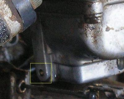
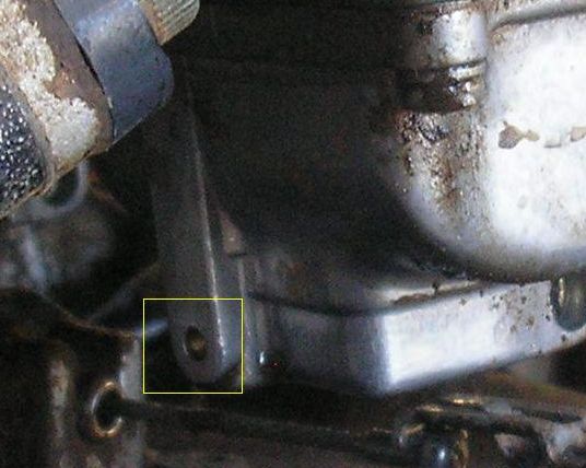
You can also see easier on the outside of the bowl the left bowl will have a plug where the passage was drilled out for the starter/choke circuit. It looks like a brass ball pressed into a hole. The right bowl will be flat. I just took a quick picture with the carbs installed. You can see the plug in the yellow square.