


misterww225
-
Posts
24 -
Joined
-
Last visited
Content Type
Profiles
Forums
Events
Gallery
Store
Everything posted by misterww225
-
Exhaust port roof shape vs power characteristics
misterww225 replied to SlowMoe's topic in Banshee Repairs and Mods
Neg. Vito's super stock pistons are cut straight across to simply advance the exhaust timing. There is extra "meat" in the piston land on these. The concept discussed here is an old method to effectively make the exhaust port top flat for a wide portion of that exhaust port. "More area plus a stronger pulse from the port "popping" open." -SlowMoe -
Exhaust port roof shape vs power characteristics
misterww225 replied to SlowMoe's topic in Banshee Repairs and Mods
Hmmmmm... http://bansheehq.com/forums/index.php?showtopic=114131 -
The CDI is charged by the stator. More specifically, a capacitor within the CDI is charged. When this capacitor is discharged into the coil the energy within the capacitor transfers to the coil, creating a spark. The energy within a capacitor is E=1/2 CV^2. Simply stated, the energy in a capacitor is only a linear function of the capacitor value, however, the energy in a capacitor is the SQUARE of the voltage. This means even a small increase in the stator voltage will dramatically increase the energy discharged into the coil and transferred to the spark plug. Therefore, just a few more turns on the stator will dramatically increase the spark energy. On the other hand, the capacitor has a voltage limitation when it begins to break down and dissipate energy in the form of heat and gradually degrade, eventually failing. A modest increase in the stator windings, I.E. voltage, can retain a reliable CDI system while increasing spark performance.
-
If anything, I would support putting on two(2) stock carbs per cylinder, as opposed to going to one large carb. The rationale is smaller carbs atomize fuel better and have better throttle response. Two(2) 26mm carbs are roughly equal to the same area as a single 37mm carb., and I would suspect would provide more top-end HP as well as acceptable throttle response. Why don't one of you guys with a lot of time and energy see if that works for ya? Tuning 4 carbs would keep your hands busy.
-
Need some advise! Please help!
misterww225 replied to VooDooBanshee's topic in Banshee Repairs and Mods
A lot of times the flywheel key shears because of severe detonation. You might want to make sure your racing fuel is a good batch. -
When starting from a dead stop, larger flywheels are used to store kinetic energy to supplement the engine's torque. When you dump the clutch, the energy stored in the flywheel will tend to keep the engine RPM constant, therefore giving a harder launch. When shifting from gear-to-gear, the RPM will, again, tend to stay constant, which gives you a "jump" when shifting. The down side of a heavier flywheel is that while in a gear the engine will rev more slowly, as it is storing energy into the flywheel. Since, as mentioned earlier, drag racing is all about the launch, a heavier flywheel, not a PVL or shaved flywheel, will benefit you.
-
How close is my porting to drag?
misterww225 replied to SLORYDER's topic in Banshee Repairs and Mods
I would stagger the transfers I.E. Mains open, 0.5mm later Aux open, 0.5mm later boost ports open to produce more mid-range. -
I disagree with the ascertion 1 degree = 0.021" for that would imply 360 degrees would be a 7.56" circumference. Divide that by Pi to get the diameter of the hole pattern = 2.406" diameter. I haven't measured it but that seems a bit too small. Others say that 1 degree is close to 1mm (0.03937"). That would be .03937*360/Pi = diameter of hole pattern = 4.511". That seems a LOT closer.
-
What size domes for 100 octane
misterww225 replied to JoeHazzard's topic in Banshee Repairs and Mods
To measure the cc volume, lightly grease the cylinder to effectively "seal" it, then rotate and lock the the crank at TDC. Wipe the excessive grease off. Install the head/dome and fill the dome to the bottom of the plug threads using the syringe with oil to measure the head volume. Be sure to remove the head and clean the grease off afterwards. -
Holes appear to be 0.4375" dia. and the pressed in brass 0.439" dia. Appears to be stainless ball valve. You can modify a single feed to be a dual feed by removing the plug and adding another 90* nipple as the ball valve has been drilled through. Pingle warns against twisting the fittings (possibly because it will twist the o-ring and cause it to leak).
-
not sure what pipes to use on a 421 stroker
misterww225 replied to gmctruck1976's topic in Jetting & Exhaust Forum
At greater than 3/4 throttle you are using the main jets. With a bigger engine, it will suck harder on that single carb and make it run rich (it will missfire and "burble"). At full power when an engine is under-carbureted it will tend to run rich, whereas an over-carbureted engine will tend to run lean. I would put on the 34's and "dial it in". Sure it's twice the work, but with the top-end power gain you will see it will be worth it. -
Many ways to "skin a cat", however, forget using a distance measurement to get degrees. As you have just discovered, several other dimensions will alter the port height. Instead, find a degree wheel and attach it to your crankshaft and use a dial indicator to find TDC. With chinese tools everywhere, this should not a problem. If you can't find a degree wheel, print one out and glue it to some posterboard. Calculate the degrees for the desired timing and after bluing the cylinder, move the crank to this position. Mark along the top edge of the piston with a 90 degree dental tool. This is a reference line. Always double/triple check the degree positions and dial indicator references before cutting. Use the same brand of base gasket for marking and assembly. Final markup can be made using arbituary symetric guidelines and/or a shape developed using 2-stroke software and/or graphics software and printing/cutting with a razor. This pattern for the port(s) can then be transfered to the blued cylinder.
-
To determine the change in degrees for a rotational move, do the following. Determine the diameter of the bolt holes and multiply this by Pi(3.142). This will give you the circumference of this circle. Now divide that value by 360 to get the movement for one(1)degree. Now multiply that value by the number of degrees desired. As an example, if the diameter were 5.1" and you wanted to advance the timing 4 degrees: 5.1 * 3.142 / 360 * 4 = 0.178"
-
How close is my porting to drag?
misterww225 replied to SLORYDER's topic in Banshee Repairs and Mods
Port shape- absolutely. Your description of the results of a flat roof are right, however, as we all know a flat roof will hang a ring. I keep the roof radius to 5" and, of course, bevel the edges. When beveling the edges, remember the ring sticks out the most in the center of the port, so depending on the width of the exhaust port beyond 75%, you will need more bevel in the center to, literally, press the ring back into the piston. The angle of this bevel is fairly shallow but rounds and then blends to the port passage. Back to you question though- yes, a "flatter" roof will peak the power because the sonic wave is more defined and higher in amplitude. That it is less dispersed over time means the pulse will be at a more specific RPM range. This will turn a trail pipe into a dune pipe. The idea behind the intake shape is to improve flow. You can increase flow by decreasing the effects of eddy currents and straightening the path. Eddy currents are caused by sharp changes in the flow path. Having a smooth flow path will decrease the resistance of the flow and dramatically increase the flow rate. -
Questions about my 4 mill setup
misterww225 replied to crustydemon's topic in Banshee Repairs and Mods
I would get the CPI pipes (you will eventually get there anyway and the resale value is great). You will still have a wide power curve, but who know, you might like having a lot of "grunt" as opposed to having a machine that likes to either wheelie or looking for a gear that gets you back into the power band as will changing the timing will produce. Leaving the timing will also make it a lot easier to drive on a trail. You can always make the mods later- it really wouldn't be all that much more work for a winter project. BTW, on YOUR engine, from 190 degrees to 196 degrees means raising the exhaust 0.061". An easy way to change (if you know the timing for sure) is to remove the cylinders, ink blue above the exhaust, and with small calipers set at the 0.061", scribe a line parallel along the exhaust upper edge- then you can grind to the line and re-polish the port and bevel the sharp edges. Another method (which I prefer) is to use a timing wheel. With the engine cylinders still bolted on, place each cylinder at half way down and blue the top edge of the exhaust port. Move and lock the timing wheel to 82 degrees ATDC (to get 196 degrees) and using a small 90 dental tool, scribe a line along the piston top above the exhaust port. Do the same on the other cylinder (being careful not to rotate the wrong way and remove the bluing in the cylinder you just did). Then remove both cylinders and do the grinding/polishing. Be sure to maintain the exhaust port upper edge radius and bevel the sharp edges. -
Questions about my 4 mill setup
misterww225 replied to crustydemon's topic in Banshee Repairs and Mods
Well, not a dog, just more of a flat torque curve that never seems to "get on the pipe" but revs to the moon. To make more HP you need a dune port, not an mx port. Since the transfers have been raised to 130 degrees, you can't easily undo that to get the needed blow-down time. You can, however, change the exhaust ports. The exhaust ports should be raised to about 196 degrees but not more. The main transfers roofs should be around 3-5 degrees up and pointing about a half inch behind the piston center. The aux port roofs should be flat (0 degrees) and the front edges pointing towards the opposite aux transfer. Even with a 4mm crank the stroke is still relatively short and will make good mid/top end HP. Like I said, with the transfers now at 130 degrees, the option for HP is at a higher RPM and the pipe chosen should be one to coordinate with the port timing. As others above have mentioned, T5's or CPI's are a good choice. You are looking for a pipe length of about 24" to the start of the center section from the piston face and about 36" to the start of the stinger from the piston face. Running gas this would be about a 9600 to 10500 RPM setup- one screamin' machine you would have fun on. -
Questions about my 4 mill setup
misterww225 replied to crustydemon's topic in Banshee Repairs and Mods
Your intention seems to be a trail machine with a WIDE power-band. The combination of 30 degrees blow-down and these pipe support that. The HP numbers will be moderate and clutch mods will not be required. The 34mm carbs will work great and provide you with all-around excellent drivability and power as well. The modified cages will be adequate for this low power level. If you want more power and top-end, you can raise the exhaust to 196 degrees, install CPI pipes, add the v-force reeds, and make clutch mods at a later date. -
Wheeler Piston Scallop Mod (WS Mod)
misterww225 replied to misterww225's topic in Jetting & Exhaust Forum
... and the other pics

-
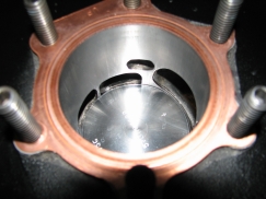
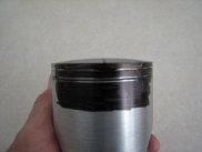
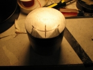
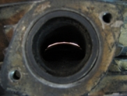
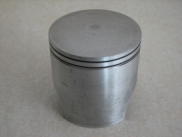
Here is a modification to increase the blow-down time and increase the exhaust pulse signal strength to the pipe. This modification is not for beginners and can be done by hand, machine, or CNC. The summary of the mod is to modify your piston dome to match the shape of the upper portion of the exhaust port (the curve of the oval). This allows more area to open for the exhaust to exit in a shorter time (degrees). One method would be to blue the exhaust side of the piston, insert it into the cylinder up to the point of the exhaust closing, and mark the piston with a dental tool (sharp narrow tool). Next mark on the piston the outer edges of the exhaust port (some thought when modifying triple exhaust ports). Finally decide on the limits of upper land on the piston, the angle of the cuts, and edge cut radiuses. Carefully cut the piston(s) with appropriate tooling. Here are some example pics of how to modify a Blaster engine. Many other layout and/or machining approaches are, of course, possible for this modification, and exhaust port timing as well as time/area need to be considered.
-
Wheeler Piston Scallop Mod (WS Mod)
misterww225 replied to misterww225's topic in Banshee Repairs and Mods
... more...
-
Wheeler Piston Scallop Mod (WS Mod)
misterww225 replied to misterww225's topic in Banshee Repairs and Mods
... more...

-
Here is a modification to increase the blow-down time and increase the exhaust pulse signal strength to the pipe. This modification is not for beginners and can be done by hand, machine, or CNC. The summary of the mod is to modify your piston dome to match the shape of the upper portion of the exhaust port (the curve of the oval). This allows more area to open for the exhaust to exit in a shorter time (degrees). One method would be to blue the exhaust side of the piston, insert it into the cylinder up to the point of the exhaust closing, and mark the piston with a dental tool (sharp narrow tool). Next mark on the piston the outer edges of the exhaust port (some thought when modifying triple exhaust ports). Finally decide on the limits of upper land on the piston, the angle of the cuts, and edge cut radiuses. Carefully cut the piston(s) with appropriate tooling. Here are some example pics of how to modify a Blaster engine. Many other layout and/or machining approaches are, of course, possible for this modification, and exhaust port timing as well as time/area need to be considered.
-
repeat...

-
PORT TIMING VALUES FOR RPM RANGE. THE FIRST DURATION IN THE XXX-XXX FORMAT IS THE MIN FOR THAT RPM. EXAMPLE: TO GET TO 9000 RPM YOU HAVE TO HAVE AT LEAST 184 EXHAUST AND 123 INTAKE EXHAUST TIMING 7500 RPM 176-178 8000 RPM 180-182 8500 RPM 183-185 9000 RPM 184-186 9500 RPM 186-188 10000 RPM 190-192 10500 RPM 193-196 11000 RPM 196-198 TRANSFER TIMING 7500 RPM 120-123 8000 RPM 121-125 8500 RPM 122-126 9000 RPM 123-127 9500 RPM 124-128 10000 RPM 127-131 10500 RPM 129-133 11000 RPM 130-134