


muggzy
-
Posts
498 -
Joined
-
Last visited
-
Days Won
2
Content Type
Profiles
Forums
Events
Gallery
Store
Posts posted by muggzy
-
-
What exactly was so bad about the tm design ? Was considering one of these as well
Don't get me wrong here. I've got a TMD case saver, chain guide and swing arm protector,and have been very satisfied with them all.
When I tried to mount up the skid plate,
1) It was more than an inch too narrow, exposing all of the sides of my frame. This is especially bad where the frame angles out for the back half of the frame. My old alum one has some of it's worst scars at these edges.
2) The mounting clips (similar to the extruded finger style you've seen on alum. skids) were made out of the same slippery material and barely reached the frame. This allowed the skid plate to shift around without much effort.
3) There was a single "finger" to hold the front that didn't quite reach the lateral frame bar. So there was nothing to keep the skid plate from sliding back the first time I hit a rock.
If it wasn't for the too narrow fit (1), I could have used the vinyl coated conduit straps used in this fab to fix problems 2 and 3, but after all I paid, why should I have to?
I will say in TMDs defense that they were really great about taking it back. The other TMD products that I own(ed), are well made, fit and work flawlessly and have held up really well. I wouldn't hesitate to buy from them again in the future.
I also considered the one Maier has on clearance for $50 but they do not accept returns on clearance items and they didn't have black.
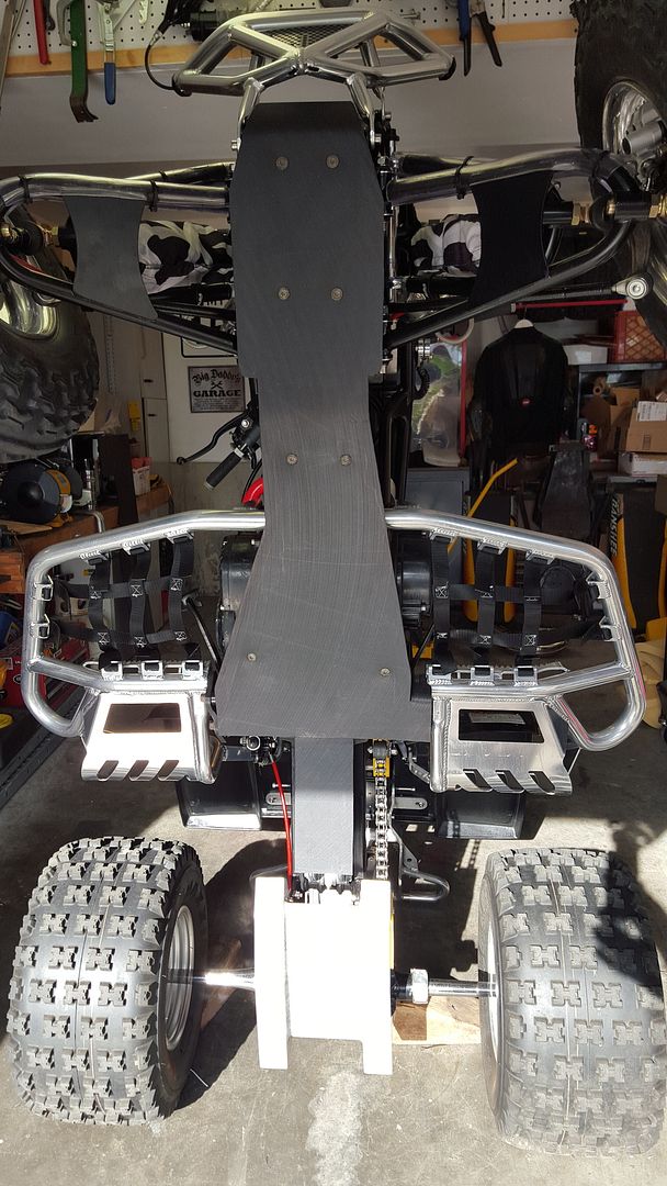
I'm sooo much happier with the way this turned out (assuming it holds up)
It's a full 1/4" thick, not just 3/16"
Enough material to do the swing arm and A-arms also and I haven't ever seen a plastic one to do all of that.
Front and side edges seem well protected
Again, we'll see how it holds up. I intentionally smacked a couple of rocks and it took it on the chin pretty well.
-
Thanks!Damn, good work.
Sent from my SM-G920V using Tapatalk
-
I'd have to find someone to cut the plastic in some small quantities to even consider it. The time to make these one-off' I'd have to charge you too much.Yup I'm jelly , how much to make one for me ? I can provide my own bolts
Thanks for the compliment though.
Sent from my SM-G920V using Tapatalk
-
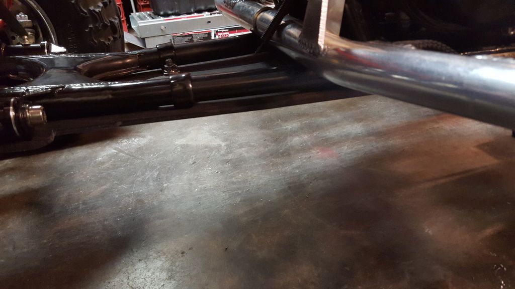
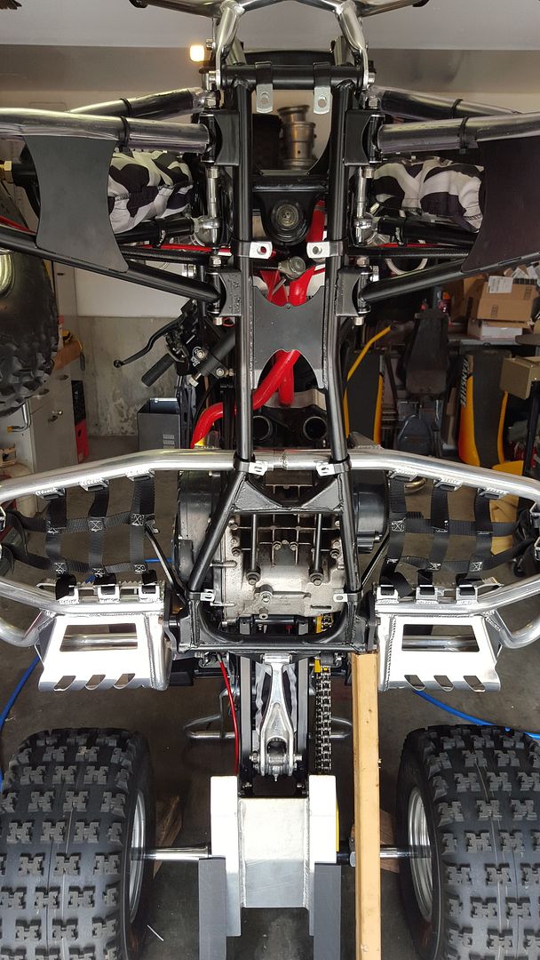
OK, Here's the first ride report:I intentionally ran a couple of good sized rocks under the center rather than running the wheels over the rocks. Definitely "glided" over them - no lurch like you get with the alum. The hits were taken on the swing arm skids;
 First time out and the A-arms are def gonna need some love too...
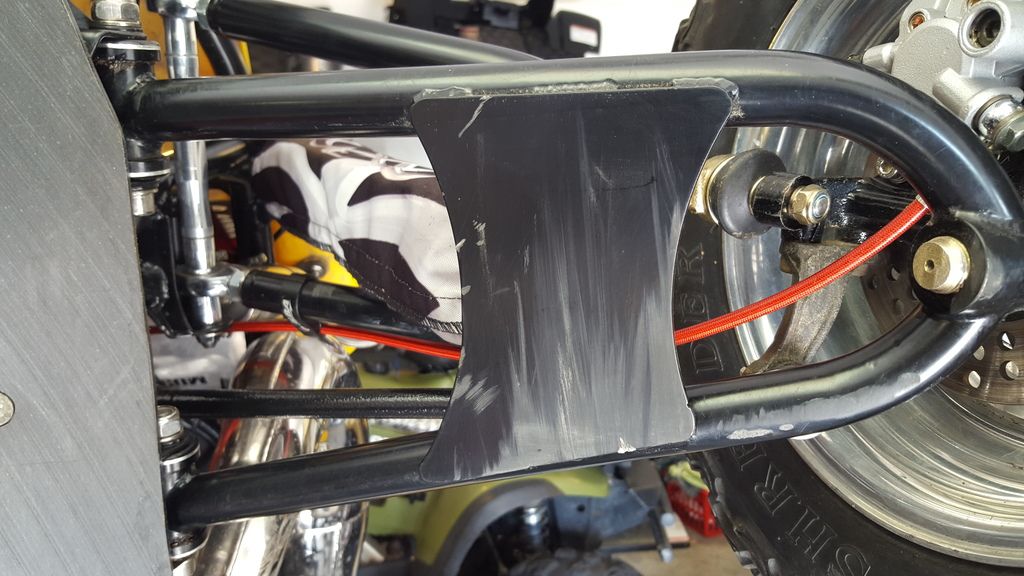
-
-
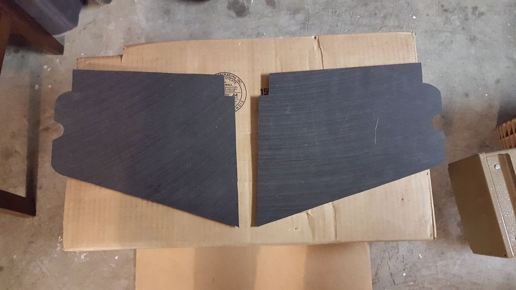
Only needed the one and I just flipped it to get both sides. Got both of them cut out today and now I gotta wait for the screws. I'd like to heat the plastic, mount it in place and use the a-arms themselves to form it around. I may change my mind about that before the screws get here though
-
 1
1
-
-
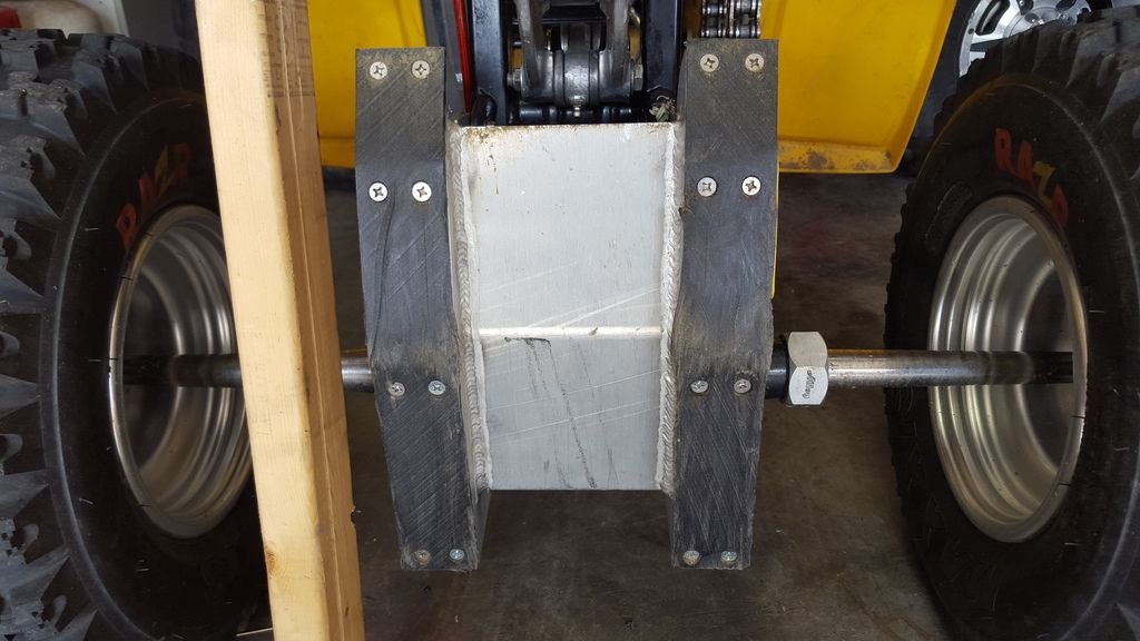
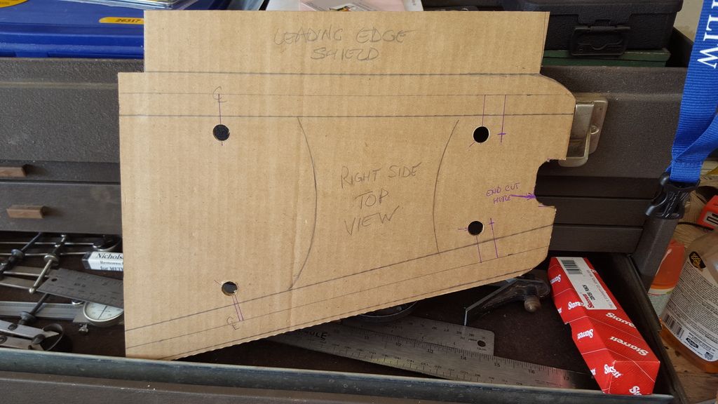
So I started the A-arms today:I have plenty of UHMW and conduit straps left, so all I needed was a set of the rotor mounting screws. Found several people selling them on ebay for $10 a set + $6 for the ride.For the template, this time I taped a piece of cardboard in place and carefully traced it from the top since I had the access. From there, I found the centerlines in order to locate the conduit strap mounting holes. I'm also gonna put a leading edge protector on it as well:
-
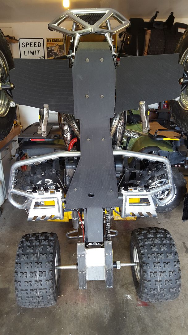
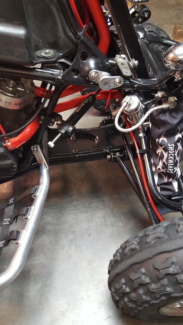
I've got enough extra material left to make some A-arm skids too. Those I'll curl around the front edges like I did for this one. But now that she's got all the most important armor, I can finally take her out. The rubber tubing I put over the A-arms will have to do. I'm seriously jonesing for a ride
 If there's enough interest, I'll post up wear reports to let you know how they behave as glides and how they hold up. I had a DG belly skid and an Armadillo swingarm skid on my my last bike and beat the crap out of them.
 -
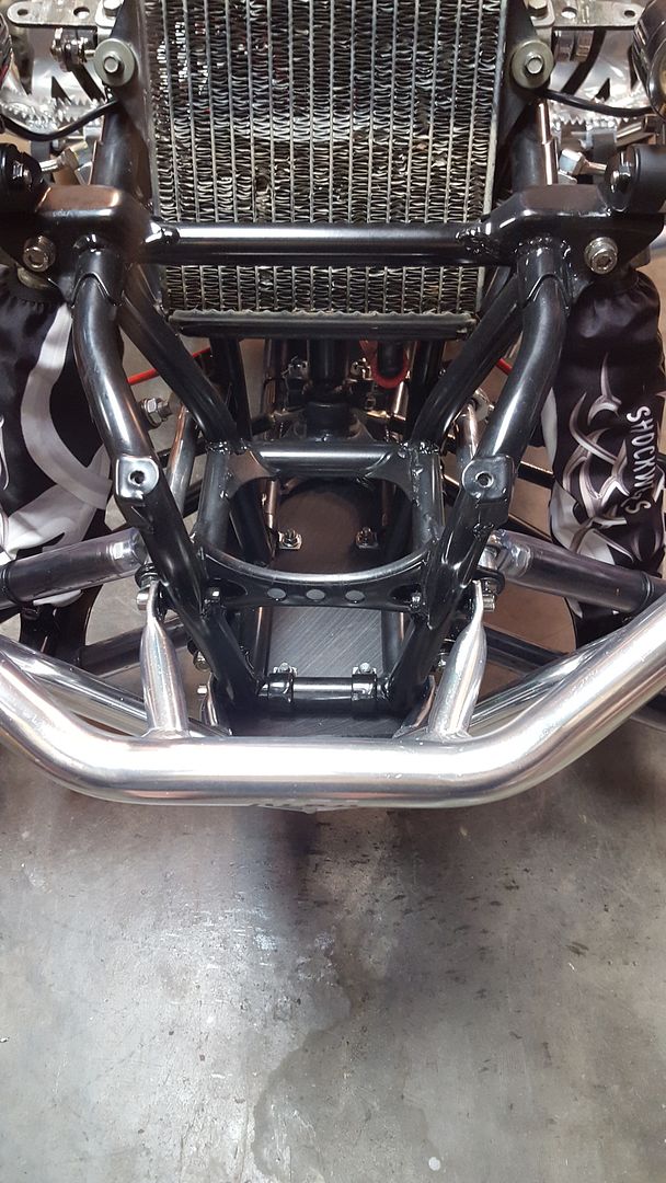
The 1/4" overhang I left ought to do the job of protecting the sides of the frame. One thing that I hated about the curled edges of the aluminum skid plate that was on my first bike was that you couldn't get the crud out of the edges. This design has a nice 1/8" gap all the way around that will allow me to pressure wash the mud out.
-
Views from the top:
-
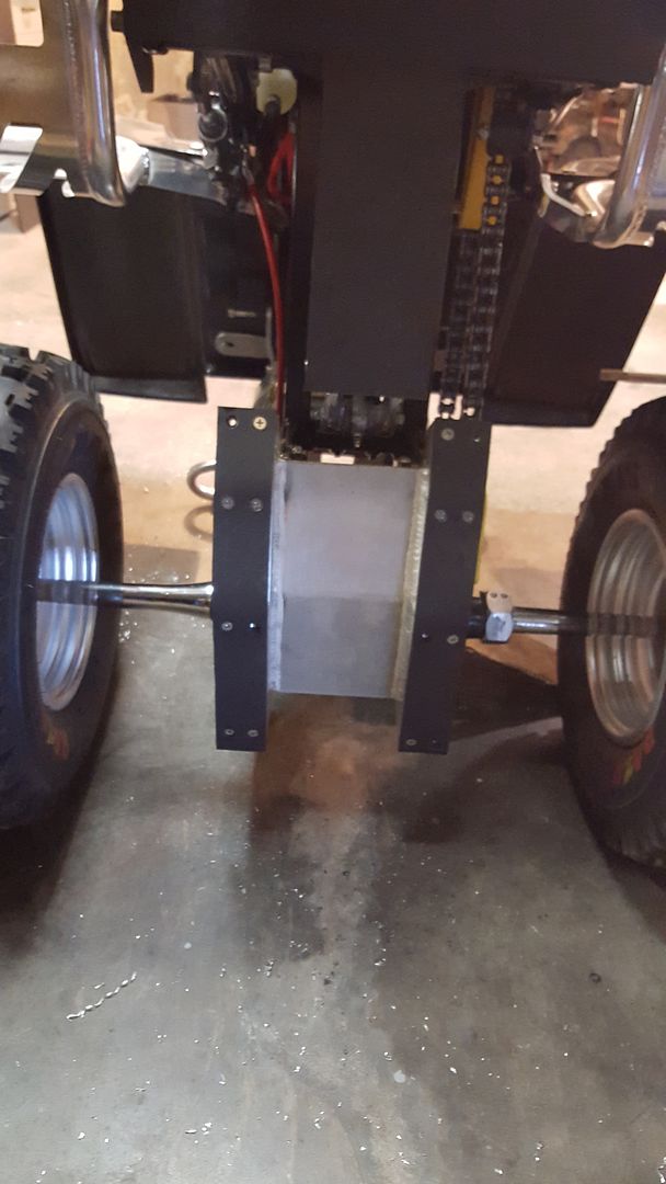
Bolted up pretty nice, but that lower right bolt at the back of the frame had to go on first. I tightened up both of the back nuts by holding them with a pair of long-reach needle nose pliers.
For the swing arm glides that i put on that skid plate, I used counter sunk M6-1.0 x 12mm FH SS screws that my local HD happens to carry but I cleaned them out of the 12 they had on hand. So yeah, I'm missing a few screws :-)
-
Straps still in place from when I test for the cardboard. I also just I notice that he swingarm skid could use some love too

-
The finished skid plate:
-
One of the nice things about working with the 1/4" thick material is even though it takes a while to heat through, it stays hot for a long time so you can get fixture on it to hold it in the shape you want once it's cooled. One of the sucky things about the thick material is that it takes a long time to cool so you HAVE to fixture most of it or you cant take a swig off your beer.
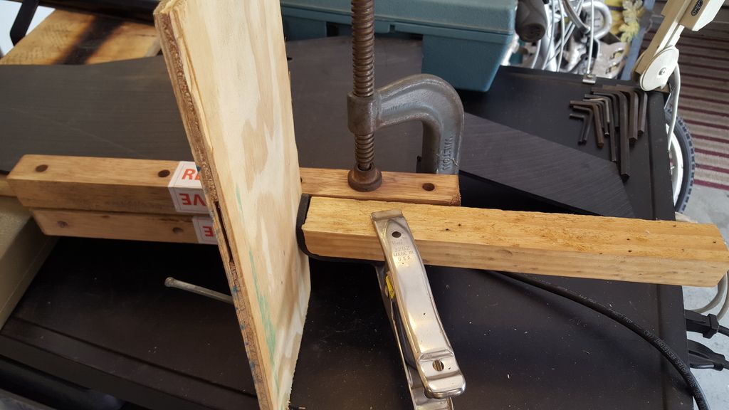 I did something similar for the front curl but forgot to snap a pic.
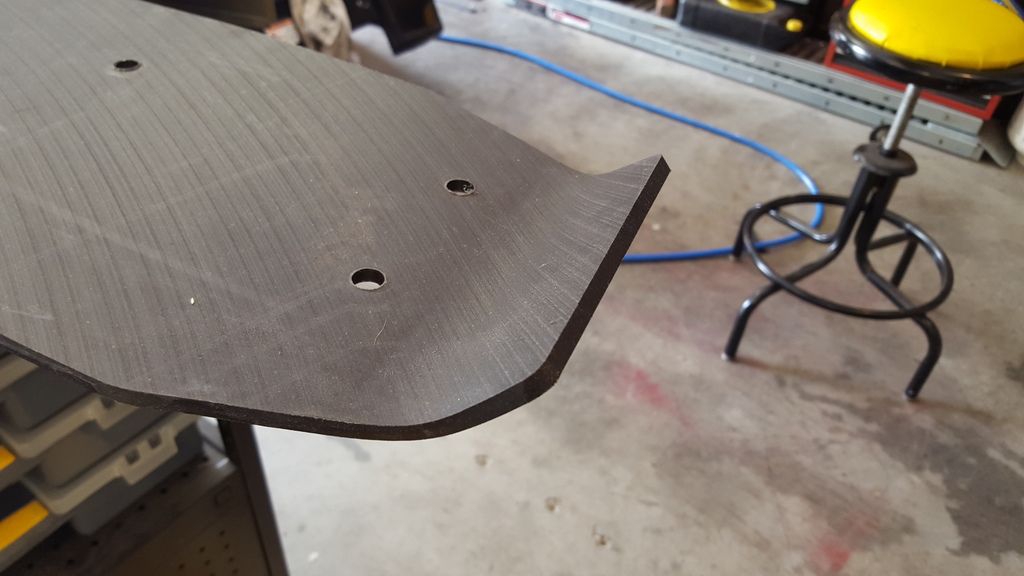
-
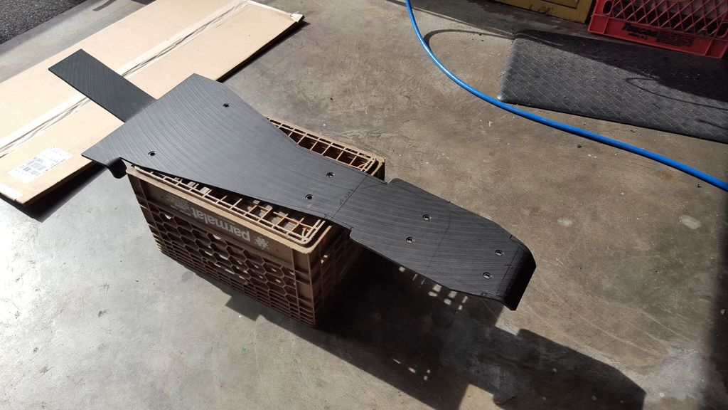
Some of the more elaborate bends I'd planned and the excess material was trimmed off. I left a 1/4" overhang on the side and still plan on curling the front.
 Here's the skid plate with the adjustments made to the perimeter but before bending
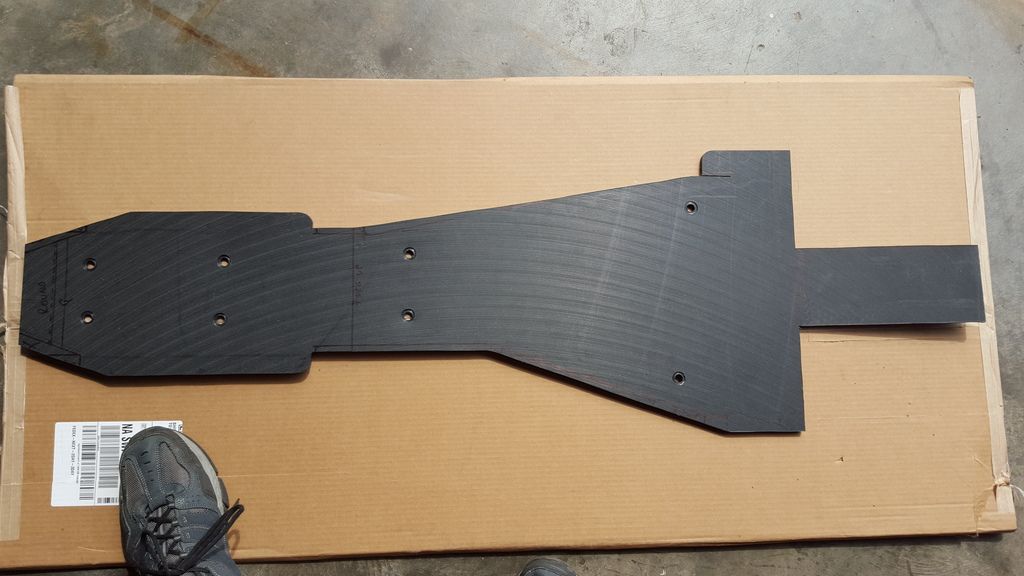
-
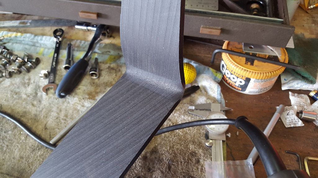
A piece of scrap material was used to make a test bend on a strip heater (a heat gun and patience could do the job too). I'm no expert but I know from experience that plastics have very different behaviors when trying to heat bend them.After seeing how much heat would be needed over long distances, I decided to bail on the idea of curling the skid plate up around the sides of the frame like the aluminum one that I had on my earlier bike. I also discovered that the material would crack if bent away from the heated side and that if I bent it back toward the heated side, the cracking "healed". Once cooled, I tried to bend it back straight to see how badly I'd damaged it, but was surprised that I couldn't get the cracks to open back up The material was heated this hot to see just how hot I would need to get a tight bend.
-
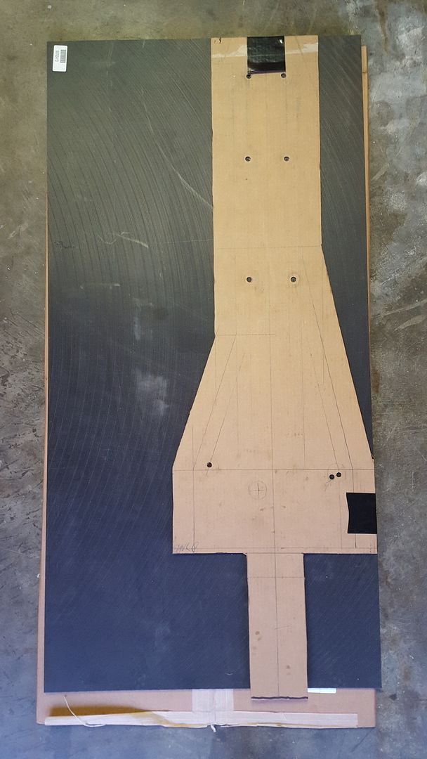
After checking and re-checking (measure twice, cut once:-), the template was cut out with a fresh blade. The holes were drilled after the cutout was positioned on the frame to see where the clamps would have room. I should mention that the "Tail" to cover the shock linkage was a last minute idea. After polishing it for the build I wanted that protected too. When I laid the uncut pattern on the plastic and saw how much extra I'd have I figured "why not?"
-
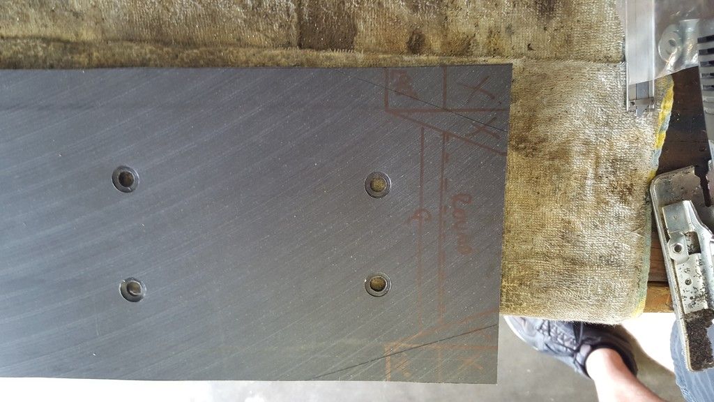
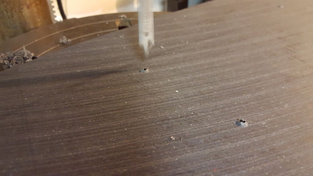
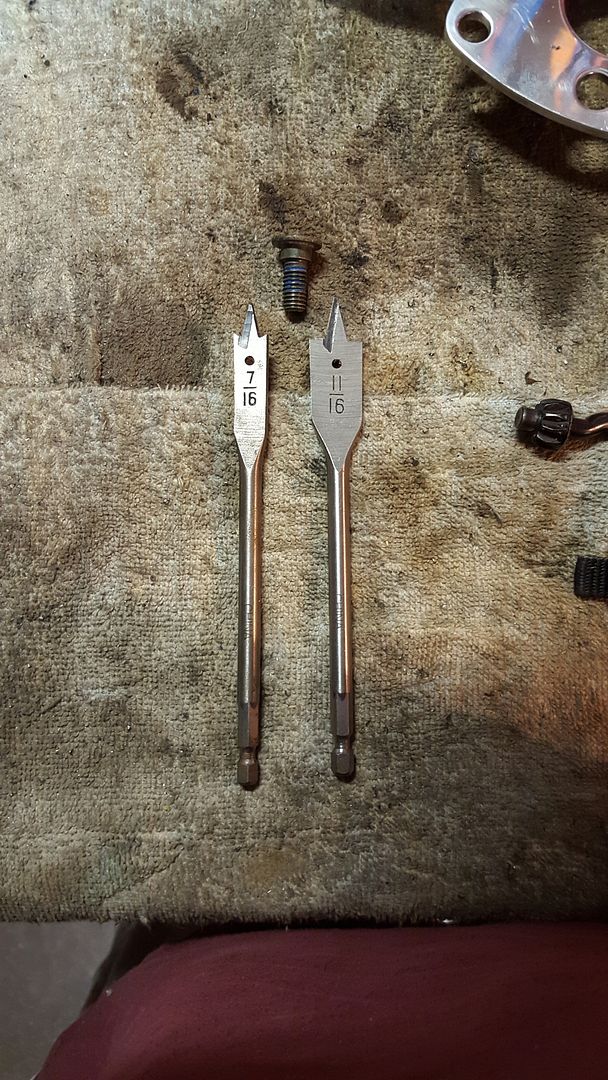
The plastic was marked with a sharp scratch-awl and cut with a new sharp jigsaw blade. Then the counter bore holes were cut with the modified larger bit 1st and the through holes were drilled from the opposite side so the points of the drills would both have enough material to center their points. It's this reason that I didn't go a little deeper with the counterbore as I would have liked.
WARNING: It should be noted here that the drilling was done with a drill press. Not the hand drill seen in the background.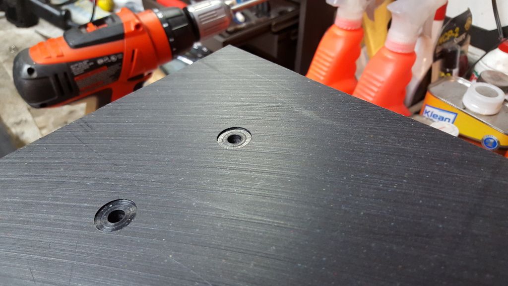
-
Another pic of the screws with the bits I used to drill the cardboard and plastic. The smaller drill was the size of the shoulder on the screw and the larger drill the size of the head. The larger drill was modified by grinding off the outer cutting edges still visible on the small drill.
-
After checking and re-checking (measure twice, cut once:-), the template was cut out with a fresh blade. The holes were drilled after the cutout was positioned on the frame to see where the clamps would have room. I should mention that the "Tail" to cover the shock linkage was a last minute idea. After polishing it for the build I wanted that protected too. When I laid the uncut pattern on the plastic and saw how much extra I'd have I figured "why not?"
-
Used the cardboard that the plastic came in to make the template. Using a sheetrock square and the pretty clean edge of the cardboard I was able to carefully transfer the frame to the cardboard. Starting at the top (front) and worked my way down noting the bend lines and critical points along the way. This part took a couple of hours. [/size][/font][/background]
The specs on the straps are 1" dia. x 1" screw offset, meaning the mtg screw hole is 1 inch from the center of the 1" pipe that the clamp is wrapped around. So I attempted to layout the centers lines of the frame, making a 1" line to the inside for the screw line. The 2" line around the outside is so I can (hopefully) bund the plastic up around the edges of the frame.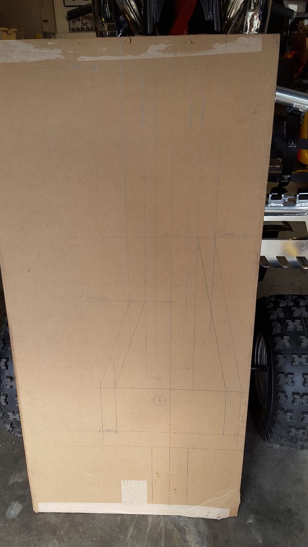
-
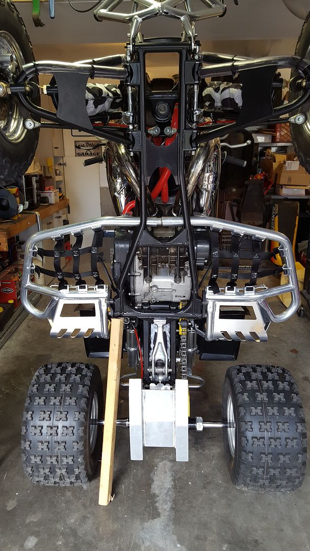
Stand the bike up and test-fit as you ...
-
Lol yeah, that might matter on a drag strip. Not sure it'll make much difference in the woods. Definitely more *bush*dynamic :-)Makes sense for sure to cut them + now your more aerodynamic
Sent from my iPhone using Tapatalk
Sent from my KFOT using Tapatalk
-
Here's the "How to" skid plate build...
http://bansheehq.com/forums/index.php?/topic/183231-making-my-own-plastic-uhmw-skid-plate/?p=1739516


Making My Own Plastic UHMW skid plate
in Banshee Appearance
Posted
Sent from my SM-G920V using Tapatalk